User Manual
Everything you need to know to build, simulate, and share circuits in EveryCircuit.
Schematic
The Schematic area is where you build the circuit, set parameter values, assign labels, run simulation, and view results. Simulation starts automatically when you open a circuit.
Visualization
Animated visualization of simulation results is overlayed right on top of the circuit schematic. The example below demonstrates how various analog and digital, constant and time-varying voltages, currents, and charges are visualized in EveryCircuit.
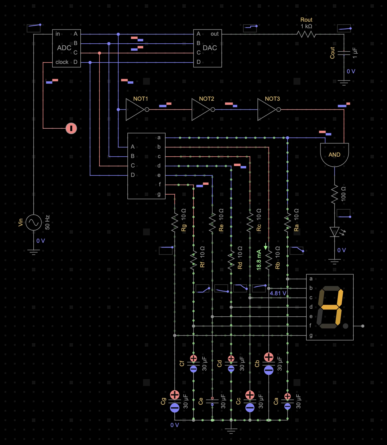
- Currents are shown as moving dots of various speed and brightness.
- Constant currents through analog components are shown as numbers like 18.8 mA.
- Digital wires are color-coded red / blue for logic high / low.
- Constant analog node voltages are shown as numbers like 4.81 V.
- Time-varying analog voltages are shown as mini-waveforms.
- Time-varying digital voltages are shown as red / blue blocks.
- Capacitor charge bulbs indicate polarity and relative charge amounts.
- LED and display segments light up gradually as the current grows.
- Component and node labels are shown as #Rout.
- Parameter values are shown as 100 Ω.
Selection
A circuit node is one or more component terminals electrically connected by wires. A node segment is a single wire between two points, such as terminals and T-junctions. One node, one node segment, one component, or multiple components can be selected at a time. Selected entities are highlighted in yellow. Making a selection clears any other incompatible selection.
Click a wire or a terminal to select a node.
Click a wire of a selected node to select a node segment.
Click a component symbol to select a component. To select multiple components, hold Shift and select a rectangular area with the mouse. Components completely or partially inside the area are added to any existing component selection. Click a component while holding Shift to add or remove individual components from selection.
Click an empty Schematic area or press Esc to deselect everything.
Editor
The Schematic can be either in editing mode or in simulation mode.
Press Esc to clear any selection, press Esc again to stop simulation and enter editing mode.
To make a connection between two nodes, enter the editing mode, click one circuit node to select it, then click another node. Wires are routed automatically — you cannot draw an arbitrary path. You have some control over wire routing by adjusting the locations of components connected by the wire. Wires can be created only in the editing mode.
Other editing actions can be done both in the editing and simulation modes. Deleting, disconnecting, rotating, and flipping components while in simulation mode switch the Schematic back to editing mode.
Editor action buttons like


 are displayed below the Schematic.
The current selection and Schematic mode define a subset of buttons displayed at any given time.
are displayed below the Schematic.
The current selection and Schematic mode define a subset of buttons displayed at any given time.
Drag a component from the Components panel and drop it onto the Schematic. You can also just click a component to drop it onto the Schematic.
Click
or press Delete or Backspace to delete selected components.
Click
or press Delete, Backspace, or C
to delete selected node or a node segment.
Click
or press C
to disconnect selected components.
This only disconnects selected component's terminals from their nodes, preserving other
connections in those nodes.
Drag and drop any component to move it to a desired Schematic location.
Drag and drop selected components to a desired location or use arrow keys ⬅ ⬆ ⮕ ⬇.
Click
or
 or press F
to flip selected components. Not all components can be flipped.
or press F
to flip selected components. Not all components can be flipped.
Click
or
 or press R
to rotate selected component. Some components have a limited set of allowed
rotations, and some components are not allowed to be rotated at all.
or press R
to rotate selected component. Some components have a limited set of allowed
rotations, and some components are not allowed to be rotated at all.
Drag an empty Schematic area with the mouse or use arrow keys ⬅ ⬆ ⮕ ⬇ to pan the Schematic when nothing is selected.
Use the mouse wheel, trackpad zoom gesture, or and keys to zoom.
Click
 or
or
 to undo or redo your edits.
Parameters
The Parameter table appears at the bottom-left corner of the Schematic when a component
or a node is selected. The table may be collapsed to make room for the Schematic.
Click
 or
in the table header to expand or collapse it.
or
in the table header to expand or collapse it.
Enter a
Enter a parameter value like
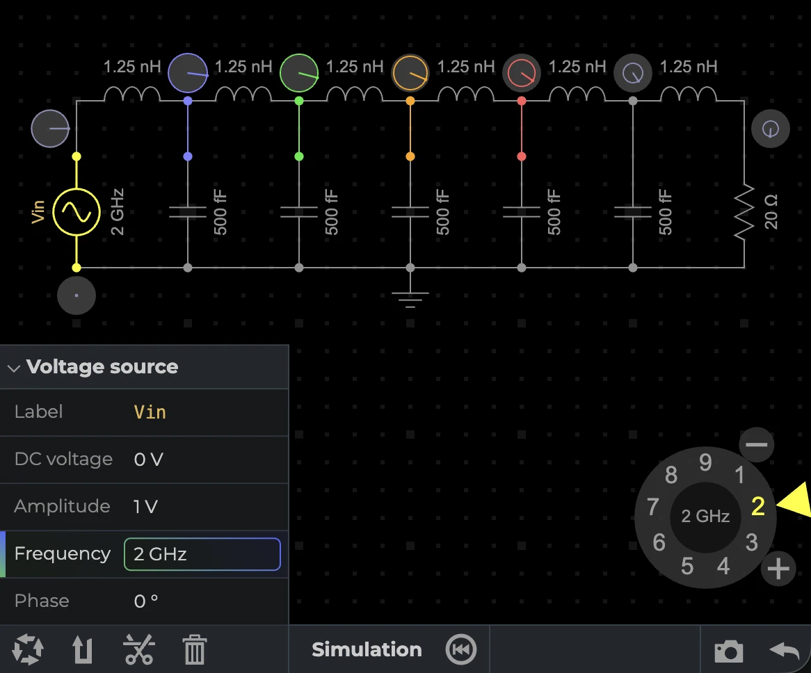
Sometimes it is desirable to gradually ramp up or adjust parameter values during simulation.
You can do this with the Knob that appears in the bottom-right corner of the Schamatic when
a parameter is selected in the Parameter table. The Knob allows you to adjust parameter
values in a continuous manner by moving the Knob slider with the mouse. You can also click
individual Knob values
There are two global circuit parameters. The
Simulation
EveryCircuit runs a SPICE-like simulation engine custom-built for real-time interactive
simulation. Simulation controls


 appear at the bottom of the Schamatic when component and node selection is cleared by pressing
Esc. Simulation starts automatically when a circuit is opened.
appear at the bottom of the Schamatic when component and node selection is cleared by pressing
Esc. Simulation starts automatically when a circuit is opened.
Click
to start or resume a time-domain transient analysis. Animated visualizations of
node voltages and component currents are displayed on top of the Schematic. You can adjust parameter
values while simulation is running and see how the circuit responds in real time.
Click
to start a frequency-domain small-signal AC analysis. AC analysis requires that the circuit
has at least one sinusoidal voltage source and no pulse sources. When analysis starts, all
sinusoidal sources are locked to one input frequency. While the analysis is running, voltage
phasors are displayed on top of the Schematic for all nodes. You can adjust parameter values,
including the input frequency, and see how the circuit responds in real time.
Click
or press Space to pause transient analysis.
Click
or press Esc to terminate simulation and enter editing mode.
Click
or press S to adjust
One way to kick-start free-running oscillation is injecting some random noise into
the circuit. While time-domain simulation is running, grab an empty Schematic area with
the mouse and rapidly shake it back and forth to inject noise. You will see a flash message
Sometimes the simulation engine will fail with
Oscilloscope
The Oscilloscope appears at the top of the Schematic when it contains traces. Up to four traces may be added. The oscilloscope can be minimized and maximized by clicking it.
For transient analysis, the oscilloscope shows all signals overlayed. Voltages
share their common Y axis, and currents share their common Y axis.
Click
 or press W to add the voltage at a selected node or the current through a
selected two-terminal component.
or press W to add the voltage at a selected node or the current through a
selected two-terminal component.
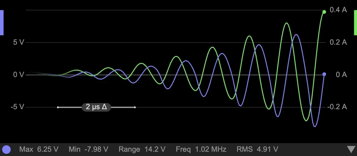
Measurements for one of the oscilloscope traces are shown just below the oscilloscope.
For transient analysis,
Click
 or press W to remove the trace of a selected node or component.
The
When analysis is paused, two vertical cursors appear for measuring the trace values and deltas. The absolute time value is not measured, only the time delta is shown.
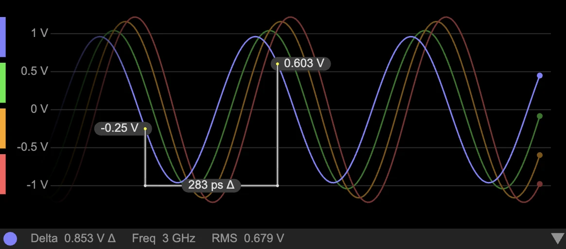
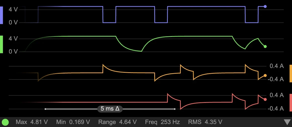
The oscilloscope can enter a Stack mode where all traces have their own Y axes and appear one below another, which is convenient for viewing transition timing of two or more traces. To enter the Stack mode, grab and drag the oscilloscope down with the mouse. Drag up to exit.
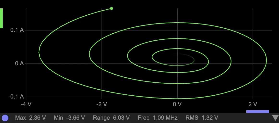
The oscilloscope can enter XY mode where one trace serves as the X axis variable instead
of the time, which is useful for viewing IV curves, hysteresis, or evolution of oscillator
orbits. To enter the XY mode, add two or more traces to the oscilloscope, select a node or
component corresponding to the desired X axis variable, and click
 .
To exit the XY mode, select the X axis node or component and click
.
To exit the XY mode, select the X axis node or component and click
 .
.
For AC analysis, the Oscilloscope shows the Bode plot frequency response for a node voltage. Although up to four voltages can be added, magnitude and phase are shown for one voltage at a time. Another voltage can be shown by selecting its node in the Schematic. The frequency range is controlled by panning and zooming inside the Oscilloscope with the mouse.
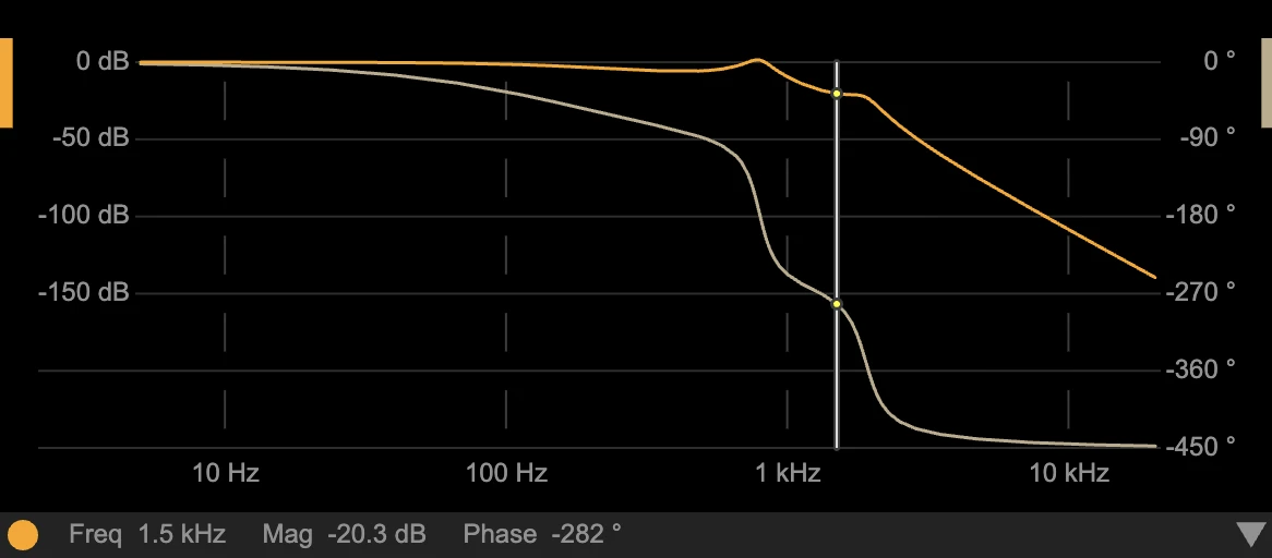
Measurements for
Bode plot typically displays magnitude in decibels (dB) computed as
$20 \log_{10}(V_{out}/V_{in})$
that represents a transfer function from input to output
$V_{out}/V_{in}$.
Transfer function magnitudes of 0 dB, -20 dB, and -40 dB correspond to
1x, 10x, and 100x reduction in sine wave amplitude. To provide better intuition, EveryCircuit
Bode plot displays output voltage as
$20 \log_{10}(V_{out})$
rather than transfer function. If you are looking
for a transfer function, set the input source amplitude to 1 V, such that
$V_{out}=V_{out}/V_{in}$.
In most cases you don't have to do anything as the sinusoidal voltage source has
Navigation bar
The bar across the top of the screen.
-
 starts a new circuit.
-
 searches Community circuits.
-
 Overflow menu:
Full screen toggles full screen mode.Settings for current direction, IEC and ANSI or IEEE
  symbols.
Gallery showcases 100,000 circuits at https://everycircuit.com/gallery.What's new lists major changes across EveryCircuit versions.Code of Conduct for publishing circuits and interacting with Community.Sign out signs you out of your account.
- @Username shows your user profile if signed in, otherwise
Sign up andLog in are shown.
Header bar
The UI outside of the Schematic area is organized into four collapsible panels.
Collapsed or not, panel headers are always visible in the Header bar just below the Navigation bar.
The Header bar shows panel names like
Examples Workspace Community Bookmarks Trash panels are shown one at a time.Circuit panel shows circuit details, including a full text description, comments, etc.Components panel contains a library of circuit components like

 .
.Muse AI panel lets you chat with @Muse — an AI circuit design agent and tutor.
While collapsed, panel headers are arranged left-to-right in the order listed above.
Expanded panels move to the left, except for the
Click panel name or the
next to it to expand the panel.
Click panel name or the
next to it to collapse the panel and make room for the Schematic.
Explorer
The vertical panel on the left shows a list of circuits. The list is selected in
the Navigation bar via Explorer tab buttons


 .
Selected Explorer tab is highlighted as
and its name is shown in the Explorer header:
.
Selected Explorer tab is highlighted as
and its name is shown in the Explorer header:
- Examples
- Workspace
- Community
- Bookmarks
- Trash
The Explorer may be collapsed to make room for the Schematic.
Click
or
in the panel header to expand or collapse the Explorer.
For each circuit in the list, the thumbnail, the title, and the description snippet are shown.
For user-generated circuits, the author username and the date the circuit was last saved are
also shown, for example,
@Username
2 weeks ago.
Private circuits
 are only visible to you.
Unlisted circuits
are only visible to you.
Unlisted circuits
 are only visible via a circuit link like
https://everycircuit.com/circuit/6392969587326976
that you can share with others.
A teacher might share a circuit link like this with students.
Public circuits are visible to anyone in the Community and on the Web.
Public circuits show Community engagement statistics:
are only visible via a circuit link like
https://everycircuit.com/circuit/6392969587326976
that you can share with others.
A teacher might share a circuit link like this with students.
Public circuits are visible to anyone in the Community and on the Web.
Public circuits show Community engagement statistics:
 Number of bookmarks.
 Number of comments.
 Number of views, excluding author views.
 Time spent viewing, excluding author time.
Circuits are awarded golden badges
for 10+ bookmarks, 10+ comments, 50+ views, and 2.5+ hours spent, excluding engagement by the circuit author.
Click a circuit thumbnail like
to open the circuit, show its details and schematic.
Click
next to the circuit title to expand its full description inline in the Explorer.
Examples
The Explorer shows a list of example circuits when
is clicked in the Navigation bar.
Workspace
Click
in the Navigation bar to show your saved circuits. Your most recently saved circuits are listed first.
You can toggle between
Click
to create a copy of your circuit — it will appear in the Trash tab.
Trashed circuits can be recovered.
Click
to delete your circuit — it will appear in the Trash tab.
Community
Click
in the Navigation bar to show public circuits.
Most recently published circuits are listed first.
You can toggle between
Click
to bookmark a circuit — it will appear in the Bookmarks tab.
Click
in the header of the expanded Community to show
Search community circuits...
input where you can enter search keywords to find a circuit you are looking for.
Bookmarks
Click
in the Navigation bar to show the circuits you bookmarked.
Click
to remove the circuit from bookmarks.
Trash
Click
in the Navigation bar to show your trashed circuits.
Click
to restore a trashed circuit — it will appear in the Workspace tab.
Click
to delete the circuit — you will not be able to recover it.
Circuit
The
or
in the panel header to expand or collapse it.
To save a copy of someone else's circuit, open the circuit, and click
.
To save your own circuit, select privacy status
Click
in the header to bookmark another user's circuit — it will appear in the Bookmarks tab
of the Explorer panel.
Click
 in the header to add a comment to another user's circuit.
Enter comment...
input will become focused in the
in the header to add a comment to another user's circuit.
Enter comment...
input will become focused in the
Click
 in the header to show URL of another user's circuit.
All
in the header to show URL of another user's circuit.
All
Description
You can write circuit descriptions with clickable component labels, node labels, user mentions, circuit links, Markdown, and LaTeX math. Here are a few examples of rendered descriptions and corresponding description text:
A B | X
-----------
0 0 | 0
0 1 | 1
1 0 | 1
1 1 | 1
```
Comments
The
Enter your comment in the Enter comment...
input and click
Click
to delete your own comment.
Click
to report another user's comment that violates
Code of Conduct.
Components
The Components panel shows a list of circuit components.
The Components panel may be collapsed to make room for the Schematic.
Click
or
in the panel header to expand or collapse it.
Click
in the header of the expanded Components panel to show
Search components...
input where you can enter a component name you are looking for.
When collapsed, the components are arranged horizontally in a compact manner. When expanded, the components are organized into named groups:
Independent sources 


Resistive


Reactive 


Switches 


Operational amplifier 
Controlled sources 


Diodes 


Transistors 


Logic sources 

Logic gates 


Latches 


Integrated circuits 


Meters 


Click
next to a component group name to expand the group and show individual component names.
Expanding the
- Diode
- Zener diode
- LED
- RGB LED
- 7-segment display
Muse AI
The
or
in the panel header to expand or collapse it.
Ask @Muse to explain, debug, build, or modify your
circuits by entering a prompt into the input field
Ask to explain or make a circuit...
and hitting Enter. The number of prompts in one chat is limited to 10 —
start a new chat if you run out of prompts.
The circuit you currently have open is automatically
attached to your prompt as a mini-thumbnail like
.
The circuit generated by @Muse is automatically
opened in place of your current circuit, but the Circuit panel remains collapsed to
make room for the Schematic. You can save generated circuit normally by clicking
In its responses, @Muse will label circuit nodes and components and make use of those clickable labels like #C2 and #Vout in generated responses to refer to specific parts of the circuit.
Click
 in the thumbnail corner to remove the attached circuit.
Click
Click
in the panel header to view chat history where you can load a recent chat.
Signed in users are granted a chat quota that resets periodically.
To use your quota more efficiently, start a
@Muse is an early experimental AI and can make
mistakes. It will sometimes generate circuits with component placement that requires
manual adjustment. Help us improve the quality by rating
good
and
bad
responses and adding written feedback.